What Is The Difference? WS2818 VS WS2811 /USC1903 magic color digital led strip
Compare with the ws2818 with ws2811 ucs1903 digital led strip
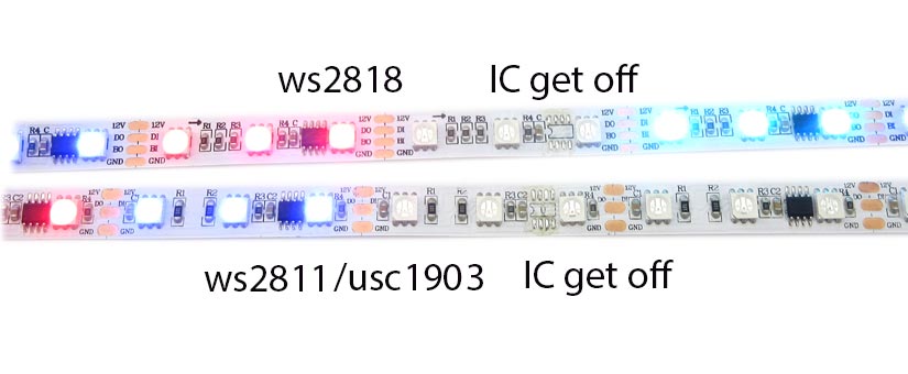
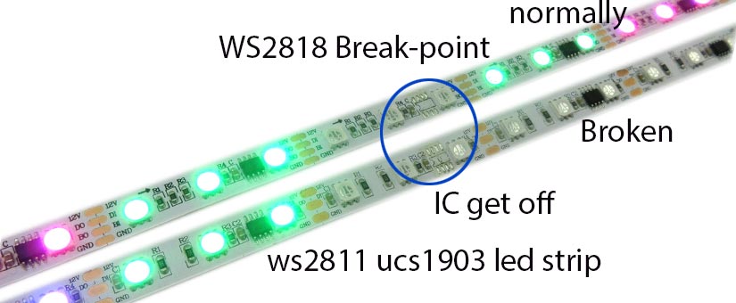
The image is mainly about the difference between the work principle of WS2818 and WS2811 LED strip. The most obvious difference is: when the IC one of the WS2811/UCS1903 was broken, it will affect the other led working, but the WS2818 will not appear above situation.
The features of ws2818:
1)Break-point transmissoin led strip(same with ws2813),can replace ws2811 ucs1903
2)Programmable full color led strips—WS2818 IC
2)30/60pcs led per one meter
3) individually control ———-1 ic& 3led chip
4)Standard Reel Length: 5meter/roll, also can be customized.
5) Cutted: 3 integrated RGB LEDs per segment, can be cutted per 3LED.
you can cut this stuff pretty easily with wire cutters, there are cut-lines
every 0.65”/3.33cm(1 LED each), Solder to the 0.1” copper pads and you’re good to go.
6)Power supply: You must use a 12 DC power supply to power this strip, do not use higher than 12V or you can destroy the entire strip
7)4 PIN JST SM connector(non-waterproof)soldered in each end of strip,extra 2single wire for powering in input side
8)Customised length available
Know more about ws2818:
WS2818 is a 3-channel LED driver control circuit, its internal include intelligent digital port data latch and signal reshaping amplification drive circuit. Also include a precision internal oscillator and a 12V voltage programmable constant current control part, which achieves highly consistent color effect.
WS2818 has strong features in Signal Break-point Continuous Transmission, it adopts dual signal transmission, these signals are able to work together without interaction. The user can select the first chip DIN/BIN as the control signal input pin, and the follow-up cascade chips will automatically identify the output signal released by the first chip which not to affect the whole display effect.
WS2818 adopts Single-line Return-to-Zero communication protocol. After the chip gets power-on reset, the DIN port receive data from controller, the first chip collects initial 24bit data then sent to the internal data latch, the other data which reshaping by the internal signal reshaping amplification circuit sent to the next cascade pixel through the DO port. The data reduced 24bit after transmitted through every pixel. Since WS2818 adopts auto-reshaping transmit technology, making the pixel cascade numbers are not limited to the signal transmission, but to signal transmission speed. When BIN works as control signal receiving interface, its control data is 24bit more than the DIN interface, so as to ensure that the two ways to control the number of pixels is the same
Based on the received 24bit data, the internal data latch generates different duty cycle control signals in the OUTR, OUTG, OUTB port. All chips synchronous send the received data to each segment when the DIN port input a reset signal. It will receive new data again After the reset signal finished. Before a new reset signal received, the control signal of OUTR, OUTG, OUTB pin unchanged. The chip exports PWM data to OUTR, OUTG, OUTB pins, after receive a low voltage reset signal the time retain over 300us


